How to Installation of Jib Crane?
Installation of Jib Crane
Installation instructions for Jib Crane (attached with pictures)
(270-degree rotation)

- Foundation fabrication of jib crane
1.1. Placement of foundation embedded parts (see Figure 1)
1.1.1. Connect the embedded bolt and the base plate as shown in the figure. The embedded bolt thread of the base plate or the upper part of the ground shall be guaranteed to be 75mm~80mm, and the upper and lower nuts shall be tightened.
1.1.2 Put the assembled foundation embedded parts into the pit according to the construction drawing and fix them, one of which is an extended embedded bolt and a grounding pile.
1.2 Pouring of pit concrete
1.2.1. Place the power supply pipe about 150 mm from the ground as shown in the figure (the inner diameter is enough to cross the power supply line).
1.2.2. When pouring concrete, the concrete strength shall not be less than C20 (note that the height shall be about 65mm lower than the ground, and the thread exposed to the concrete must be kept clean).
1.2.3. The jib crane can be installed after the concrete is maintained for 3 weeks, and the last two grouting are consistent with the ground leveling.

- Installation of jib crane column (as shown in Figure 2, for jib crane with foundation embedded parts)
2.1. Lift the column vertically, align the bottom plate hole with the foundation bolt, and put it down gently.
2.2. Fix the column base plate with washer 4, spring washer 3 and nut 2.
2.3. Tighten the nut 2 slightly.
2.4. Measure whether the column is vertical to the ground with a level ruler, and at the same time measure whether the upper plane of the upper swivel arm support 1 of the column is horizontal. If not, adjust the height of the nut 2 and the foundation nut 5 to keep it horizontal.
2.5. Tighten the nut with a torque wrench.
2.6. Torque is M20: 210 N · m, M24: 320 N · m, M27: 450 N · m
2.7. M30:600 N·m,M36:1000 N·m
Be careful:
When adjusting the level, do not unscrew the nut 2, only loosen it, otherwise there will be a risk of column toppling.

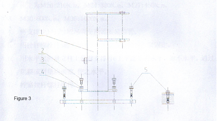
- Installation of jib crane column (as shown in Figure 3, for jib crane with large base plate)
3.1 Installation of large base plate of slewing crane foundation
3.1.1. Place the large base plate on the concrete floor where the jib crane must be installed and adjust the level. (The strength of ground concrete shall not be less than C20, and the thickness shall not be less than 200mm.)
3.1.2. In the holes around the large base plate, use the impact drill to drill holes on the concrete to install the anchor bolt of the anchor. The parameters of the drilling are shown in the following table.
3.1.3. Fasten the large base plate with the anchor bolt of part 5.
Product name, model, hole diameter (mm), bolt length (mm), hole depth (mm), maximum fixture thickness (mm), wrench specification (mm)
Heavy Ampere Bolt HSL-TZM16/25 24 152 125 25 24
Heavy Ampere Bolt HSL-TZM20/30 28 190 160 30 30
3.2 Installation of jib crane column
3.2.1. Lift the column vertically, align the bottom plate hole of the swing arm crane with the large bottom plate hole, and put it down gently.
3.2.2. Fix the column base plate with washer 4, spring washer 3 and bolt 2.
3.2.3. Tighten bolts 2.
3.2.4. Check whether the column is vertical with a level ruler. If the column is not vertical, make the column vertical by adjusting the level of the large base plate.
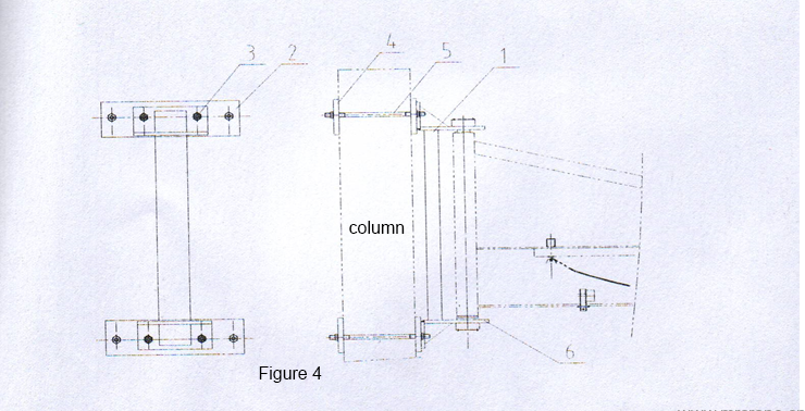
- Installation of wall hanging support block (BXDB type is shown in Figure 4)
4.1. Tighten the support block 1 and clamp block 2 with high-strength bolts 3 and torque wrench.
4.2. The torque is M20: 210N · m, M24: 320N · m, M27: 450N · m.
4.3. M30:600N·m,M36:1000N·m。
4.4. Lift the support block 1 and clamp block 2 to the required installation position.
4.5. Lightly tighten the clamp block 2 and clamp block 4 with the pull rod bolt 5.
4.6. Use a level gauge to measure whether the upper plane of the upper swivel arm support 6 of the column is horizontal. If it is not, adjust it by adjusting or using a cushion block to make it horizontal.
4.7 Tighten the pull rod stud nuts.
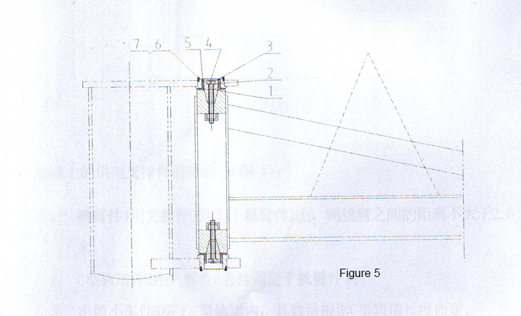
- Installation of swivel arm (as shown in Figure 5, for tapered shaft)
5.1. Clean all the protective grease on the conical shaft 1 and its mating conical hole surface, so as to ensure the reliability of its mating.
5.2. Use a crane or forklift to install the swing arm to the position as shown in the figure, and make the gap between the swing arm and the upper and lower supports approximately the same.
5.3. Thread the conical shaft 1 through the self-lubricating bearing part 5 into the conical hole on the swivel arm, and tighten the conical shaft 1 with the hexagon socket bolt 3 and the spring washer part 2.
5.4. Fix the end cover plate 4 with bolts 6 and gaskets 7.
*Note:
Check whether the column is vertical again (use the previous method), otherwise adjust it again.
Check whether the torque of the anchor nut is correct.
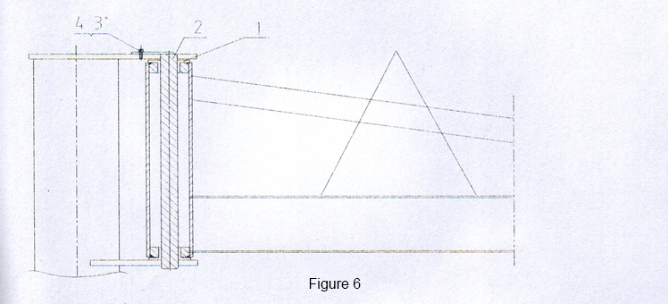
- Installation of rotating arm (as shown in Figure 6, opposite rotating column)
6.1. Assemble the self-lubricating bearing of part 1 as shown in the figure.
6.2. Use a crane or forklift to install it at the position shown in the figure.
6.3. Pass the rotating column part 2 through the support hole and the self-lubricating bearing of part 1 as shown in the figure.
6.4. Tighten bolts and gaskets 3 and 4.
Note:
Check whether the column is vertical again (use the previous method), otherwise adjust it again.
Check whether the torque of the anchor nut is correct.
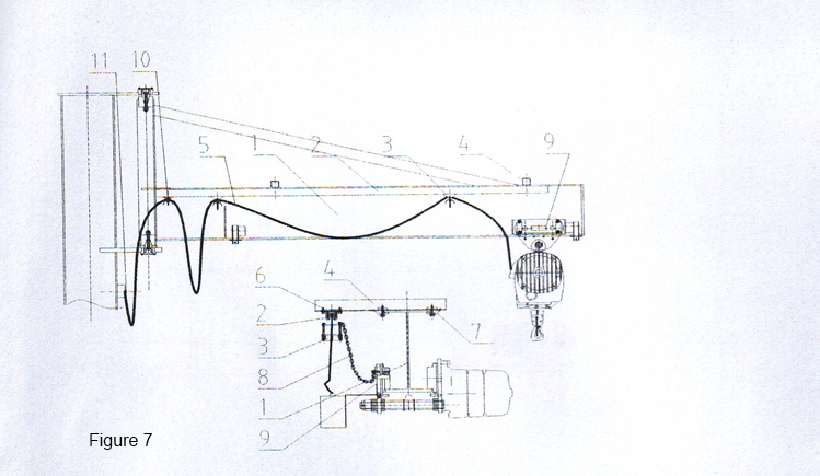
- Installation of power supply support on swivel arm (as shown in Figure 7):
7.1. The cantilever part 4 is fixed on the swivel arm part 1 with the splint part 7, and the distance between the two cantilever arms is not more than 2.5 meters.
7.2. The C-type rail part 2 is suspended and fixed on the cantilever part 4 with the splint part 6.
7.3. The cable trolley part 3 passes through the C-type track, and its quantity depends on the length of the C-type track.
7.4. The flat cable part 5 is threaded in the cable trolley part 3. Specifically, when the two trolleys are close to each other, the cable will sag about 800mm and then be clamped.
7.5. A trolley at the outermost end
7.6. One end of the flat cable is connected to the electric hoist, and the other end is fixed to the end of the C-type track with the fixed end clamp 10, and then passes through the column. The entrance is fixed with the cable fastener 11. The lower end of the cable is connected to the main switch in the column.
- Installation of main switch
8.1. The main switch is installed in the column hole to connect the input cable and output cable.
8.2. 0 bit (OFF bit) means to cut off the power supply. 1 bit (ON bit) means power on.
*Precautions:
Make sure that all joints are firm.
Ensure that the junction head cannot contact the column wall, otherwise there will be a risk of electric shock.
- Installation of electric hoist
9.1. Adjust the spacer sequence to adjust the distance between the traveling wheel flanges of the electric hoist to make it 1~3 mm larger than the width of the H-shaped steel.
9.2. Hang the traveling wheel of the electric hoist (the front end of the swivel arm faces the column).
9.3. Connect the cable lug into the electric hoist according to the drawing.
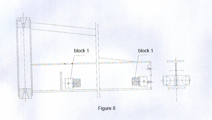
- Installation of walking wheel impactor (as shown in Figure 8)
- Use of jib crane
11.1. The jib crane must be effectively grounded.
11.2. It is forbidden to stand under the swivel arm when lifting objects to prevent danger.
11.3. After using the jib crane for a period of time, carefully check whether all fastening bolts are loose, especially the anchor bolts and the clamping bolts of the wall arm crane. If it is loose, it should be tightened before use.
11.4. The operation of the electric hoist must be in full accordance with its operating instructions. The lifting chain or lifting wire rope must be lubricated with chain or wire rope oil regularly to extend the service life of the chain rope.
11.5. It is strictly forbidden to lift objects beyond the scope of the swivel arm. It must be moved to the scope of the swivel arm before lifting.
11.6. Overload lifting is strictly prohibited.
11.7. The equipment must be subject to regular safety inspection (comprehensive inspection shall be conducted once a year, and fasteners and safety devices shall be inspected once every six months) to ensure the safe use of products.
